 +86-15916242887


News

Why do signals always "deviate"? From reflection to loss: uncovering the invisible barrier in circuits
2026-06-03
Signal Deviation Analysis
Why does a signal always "deviate"? From reflection to attenuation, uncovering the invisible barrier in circuits.
Have you ever encountered this scenario: with the same wire and signal source functioning perfectly on the board, connecting an external cable or replacing the connector causes the waveform to distort, amplitude to decrease, edges to slow down, and even communication error rates to surge; while simulations show no issues, actual tests reveal unexpected spikes, troughs, or ringing at specific frequency bands. Many engineers initially suspect problems with component quality, PCB routing, or shielding/grounding, only to discover that the true obstacle lies in an invisible yet ubiquitous factor: impedance matching. It determines whether the signal travels smoothly through the circuit and interconnects, or gets reflected at interfaces or attenuated during transmission, leading to signal deviation.
To understand why signals may deviate, the first step is to shift our perspective from the "static circuit of voltage and current" to that of "energy flow along transmission lines." When the signal's rising edge is sufficiently fast or the trace/cable is long enough, the conductor ceases to be an ideal "short connection" and becomes a transmission line with distributed inductance and capacitance. A transmission line has a characteristic impedance Z₀ (commonly 50 Ω for coaxial lines, 100 Ω for differential pairs, and 75 Ω in some RF systems); it is not a purely energy-consuming component like resistance but rather resembles the "width of the energy flow channel." When the impedance relationships among the signal source, transmission line, and load are mismatched, energy reflects at the interface, resulting in ringing, overshoot/under overshoot, steps, waveform distortion observed on the oscilloscope, or in the frequency domain, manifested as degraded S11, increased standing waves, or abnormal insertion loss.
Reflection & Discontinuity
Understanding how wavefronts react to impedance transition points.
Reflection essentially occurs when a wavefront reaches an impedance transition point and detects a change in the channel width ahead. If the load impedance equals Z0, energy is absorbed without reflection, resulting in a reflection coefficient approaching zero; if the load impedance deviates from Z0, energy is reflected back proportionally. In extreme cases, the situation is more straightforward: an open circuit corresponds to infinite impedance, where almost all energy is reflected in phase, causing the voltage to appear doubled; a short circuit corresponds to zero ohms, where almost all energy is reflected out of phase, leading to a pronounced voltage understroke. While most engineering scenarios are not as extreme as these extremes, any mismatch will still cause reflection, which superimposes on the original waveform to produce the observed signal distortion (or "run-off").
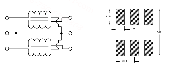
Reflections do not occur solely at "end loads"; they manifest at every impedance discontinuity: connectors, vias, line width transitions, reference plane slots, T-shaped branches, test pads, parasitic capacitance of ESD devices, and even equivalent impedance variations of seemingly ordinary capacitors or inductors at high frequencies. Numerous application articles from component manufacturers consistently emphasize "parasitic characteristics": for instance, chip capacitors behave as capacitors below their self-resonant frequency but transition to inductance above it; Ferrite Beads exhibit high impedance at specific frequencies to suppress noise, yet their DC resistance causes voltage drops and heat generation; common-mode inductors are effective against common-mode noise but introduce differential-mode insertion loss. When deployed in high-speed links or RF channels without proper selection and layout tailored to the impedance environment, these components can evolve from "firefighting tools" into sources of reflection.

Losses & Attenuation Types
Categorizing the factors that diminish signal integrity.
Besides reflection, another cause of signal deviation is loss. Losses can be categorized into several types: conductor loss (where the skin effect concentrates high-frequency currents on the copper surface, increasing equivalent resistance); dielectric loss (resulting from the loss tangent of materials like FR4 causing energy to dissipate as heat); radiation loss (where traces radiate energy outward like antennas); and energy consumption introduced by the device's own equivalent series resistance (ESR) or equivalent series inductance (ESL). Unlike reflection, losses do not produce a distinct ringing effect but lead to gradually decreasing signal amplitude, smoother edges, closed eye patterns, and reduced system margin. More problematic is that reflection and loss often coexist simultaneously.
Three Common Matching Approaches:
1Source-side series matching: A resistor is connected in series at the driver end to match the source's equivalent output impedance with line Z₀.
2Load-side parallel matching: A resistor is connected in parallel at the receiver end to ground or a specified bias voltage, equalizing the load impedance to Z₀.
3Differential termination: The differential pair is typically bridged with a 100Ω resistor at the receiver end, combined with precise differential trace design.
In practical engineering, "matching" involves more than simply placing a resistor. First, it's essential to define the operating frequency and rise-time bandwidth: while many digital signals have low fundamental frequencies, their edge bandwidths can reach hundreds of MHz or even GHz levels. Therefore, determining whether transmission-line treatment is required should be based on the ratio of signal rise time to trace propagation delay, rather than solely on clock frequency. Second, trace characteristic impedance must be carefully controlled—line width, spacing, dielectric thickness, and reference plane integrity collectively determine Z0; vias introduce inductance while pads introduce capacitance, creating local discontinuities.
In the selection of passive components, impedance matching principles remain equally critical. For instance, when implementing EMI suppression, Ferrite Beads are not necessarily "the larger the better"; their performance must be evaluated based on their impedance characteristics across the target frequency band and under DC bias conditions. Similarly, capacitors for high-speed decoupling should not be chosen solely based on capacitance value; their selection requires consideration of ESL, layout trace area, and natural resonant frequency to establish a low-impedance power supply network.